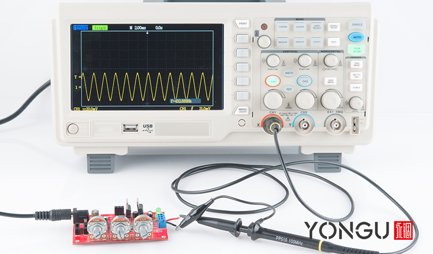
An oscilloscope is a tool for observing voltage fluctuations over time. Signals are voltages used to transmit data, such as an audio signal often used to make music play through an intercom.
The calibrated voltage signal is one of the small details displayed on an oscilloscope's screen. Vertically, you can see the voltage, and horizontally, you can see the time.
Check the behavior patterns of circuits with an oscilloscope enclosed in an electronics enclosure to see if everything is running smoothly. It will also help you pinpoint the source of any problems, such as the noise in your circuit.
TYPES OF OSCILLOSCOPE
- Analog Oscilloscope
A vertical channel uses an attenuator, a preamplifier, an analog delay line, and a vertical op-amp to boost a signal to CRT-compatible levels.
Each type of horizontal channel serves a distinct purpose. Adjustable trigger systems can have their levels set either higher or lower.
- Digital Oscilloscope
Digital oscilloscopes take an additional step before displaying the signal on the screen with an advanced high-quality metal manufactured electronics enclosure. The extra step of using an analog-to-digital converter eliminates the need for CRT-style displays by converting the signal into a digital stream. There will be more room for additional features, and the design will be more straightforward.
Most modern digital oscilloscopes, for instance, include sophisticated mathematical functions and the ability to manipulate signals.
ANATOMY OF OSCILLOSCOPE
Vertical, horizontal, trigger, and display systems are the four main components of a primary oscilloscope circuit enclosed in aluminum electronics enclosure. The various measurement techniques available today make it possible to gauge multiple characteristics.
Adjusting the vertical position and size of the waveform is possible with the help of the vertical system's controls. Input coupling, bandwidth limitation, and bandwidth optimization options are also adjustable via this knob.
The horizontal system can determine the waveform's horizontal position and size, as well as the sampling frequency and recording length.
The trigger system frees repeating waveforms, allowing you to capture them in their most acceptable form. Edge triggering and threshold triggering are just two examples of trigger systems that can be set to react to distinct conditions in an incoming signal.
An oscilloscope requires a probe to collect the data that is then analyzed. The ground clip and the probe tip are the two primary components of a probe. Connect the ground clip to the circuit's reference signal, and then use the probe tip to explore the circuit and take voltage readings at various spots.
TERMINOLOGIES OF OSCILLOSCOPE
Using an oscilloscope requires becoming familiar with a whole new vocabulary.
- Bandwidth
- Channels
- Sampling Rate
- Rise Time
- Vertical Sensitivity
- Time Base
- Input Impedance
IMPORTANCE OF OSCILLOSCOPE
In real time, oscilloscopes are utilized to see the waves produced by devices like sound cards. They may be used as an ECG for in-circuit testing and TV repair, among other things. Signals may be recorded, recovered, and examined whenever necessary using oscilloscopes with storage capabilities.
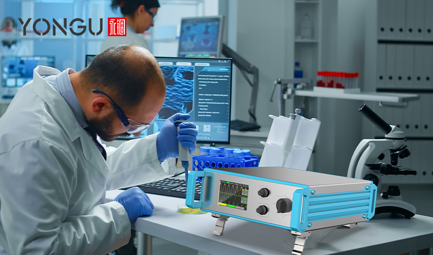
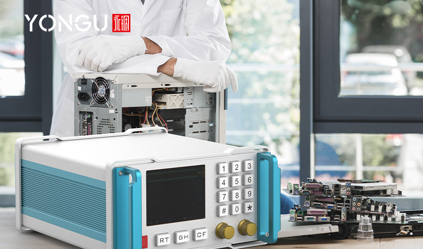
YONGU ALUMINUM Case FOR OSCILLOSCOPE
An oscilloscope electronics enclosure usually should involve the following.
A metal enclosures for electronics of an oscilloscope should be built of a magnetic material like aluminum in some cases to prevent harm to the instrument. Furthermore, any apparatus situated nearby an oscilloscope is at risk of malfunction. Electronics enclosures protect sensitive machinery from environmental hazards like magnetic interferences.
The electronic components housed within a YONGU electronic enclosures are shielded from the surroundings and maintained at a steady temperature.
The electrical components might quickly break down when exposed to vibration. Because of this, the boards and components may fail permanently. On the other hand, sensitive machinery can be shielded from outside vibrations with the help of a well-designed electronics enclosure. You may improve the stability of your rack by using a stabilizer kit. Our project enclosure are shockproof and vibration dampening, safeguarding the inside components from damage.
YONGU project enclosure are incredibly lightweight and easy to handle.
The pieces of machinery need a level of protection comparable to have some speceial design, handles and feet.
YONGU Custom Outdoor Industrial Easy Installation Electrical Industrial Control Chassis D01 269*2U
Its specific features include
- Modern appearance
- Hole drilling customization
- No minimum order Qty
- With slight aluminum wrap protective angle
- Modern design incorporating ergonomic front panel handles
- Printing: Support laser engraving and silkscreen
- Aluminum instrument case equipped with shockproof and anti-slip corner guards.
- Widely applicable to measuring instruments, analyzers, and power supplies.
- Custom cut-out and milling.
You can also contact us at +86 13326782625 or write us [email protected].


